
Pentest Chronicles
From SPI Sniffing to Keys: Extracting Clevis/BitLocker Secrets from TPM Traffic #HardwareHacking

Mateusz Lewczak
January 10, 2025
SPI Sniffing refers to intercepting communication on the Serial Peripheral Interface (SPI) bus between the processor and the TPM module. An attacker with physical access to the device can monitor this communication and potentially capture sensitive information, such as decryption keys. By exploiting this vulnerability, an attacker can gain unauthorized access to encrypted disk contents.
Setup In setups where Clevis relies on hardware such as the TPM to unlock LUKS-encrypted disks, communication between the system and the TPM module often takes place over the SPI bus. The TPM provides the decryption keys used by Clevis to unlock the LUKS volume. SPI sniffing refers to the act of intercepting and monitoring the communication on this SPI bus, potentially allowing an attacker to capture sensitive information, such as decryption keys.
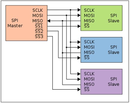
Theory SPI (Serial Peripheral Interface) is a communication protocol used for short-distance, high-speed communication between a master device (typically a microcontroller) and one or more peripheral devices. SPI is commonly used in embedded systems to communicate with sensors, displays, memory devices, and other integrated circuits. SPI is based on a single master device controlling one or more slave devices. The master initiates communication by generating clock signals and selecting the slave with which it wants to communicate. SPI uses four-wire interface:
1. SCLK (Serial Clock): Generated by the master to synchronize data transmission.
2. MOSI (Master Out Slave In): Data sent from the master to the slave.
3. MISO (Master In Slave Out): Data sent from the slave to the master.
4. SS/CS (Slave Select/Chip Select): Used by the master to select which slave device to communicate with. This line is usually active low, meaning the selected slave is activated when the signal is low.
 An attacker with physical access to the machine can attach a hardware device or use specialized tools to monitor the SPI bus traffic between the TPM and the CPU. If the attacker successfully captures the communication between the TPM and Clevis, they may be able to extract the encryption key or other sensitive data involved in unlocking the LUKS-encrypted disk. To avoid damaging the supplied equipment, the attack was carried out on an alternative device equipped with dTPM. However, the encryption configuration was preserved. The equipment used is MiniPC MSI Cubi N ADL-001BEU N200, equipped with a OPTIGA TPM SLB 9672 module.
 This document provides a detailed step-by-step explanation of the tools, hardware, and methods used to carry out an SPI Sniffing attack. It includes hardware requirements, logic analyzer setup, software configuration, and the process of extracting encryption keys from captured SPI traffic. These insights serve as both a practical guide for conducting advanced penetration tests and an educational resource for those working in information security.
Step 1. Required hardware The required hardware to perform an SPI Sniffing attack is:
1. A logic analyzer (in this case the Kingst LA2016).
2. Signal analysis software (for example, PulseView).
3. Measuring probes or other tools that allow to connect into the TPM's pins.
4. A plug-in that allows analysis of TPM communications via SPI.
 At the very bottom of the page is the code snippet that needs to be written to the pd.py and __init__.py files. These files should then be moved to the following location:
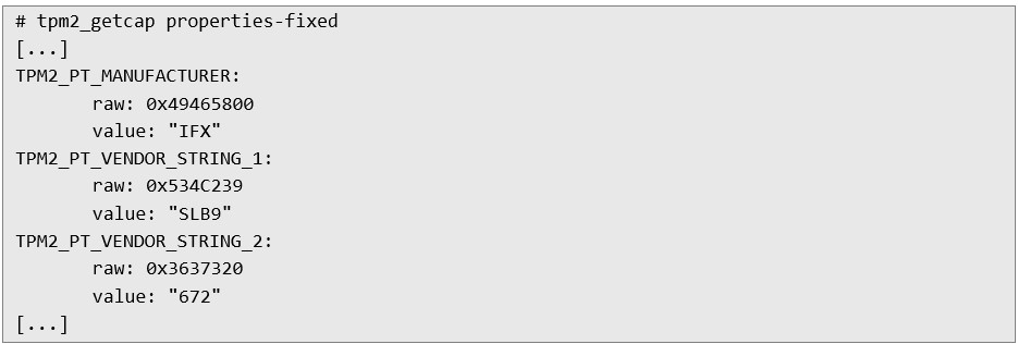
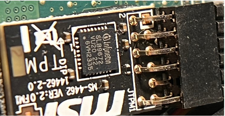
  Step 2. Connecting a logic analyzer To intercept the communication between the TPM and the processor, it is first necessary to identify the model of the module being used. This can be done in two ways:
 1. Having local access to the system shell, you can execute the following command:
 2. Having physical access to the device, read the model directly from the module. Due to its size, this usually requires the use of a magnifying glass:
  3. Then find the datasheet of the module on the manufacturer's website, in this case it is:
  4. Next, find the module's footprint and identify the following pins relatively to small white dot:
 a. Clock (SCLK),
b. Master In Slave Out (MISO),
c. Master Out Slave In (MOSI),
d. Chip Select (CS#).
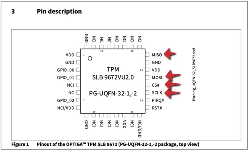 5. Knowing the position of the pins, it is now necessary to connect the logic analyzer probe to these pins:
 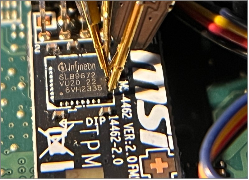 6. In addition, it is worth finding information about the voltage used by the module. Usually this is the supply voltage. It will be needed to properly set the sensitivity of the device.
 An alternative method is to take advantage of the fact that Flash memory and the TPM module are often connected in a bus (multidrop configuration). Multidrop configuration is a type of connection where the signal channels and the clock (CLK, MISO, MOSI) are interconnected, so if it is possible, it is worth connecting a logic analyzer to the Flash memory and perform analysis there. In this case, there was no such possibility. Step 3. Software Settings The next step in the whole process is to measure signals during the startup of the operating system. To do this, you need to:
1. Open Signal Analyzer:
2. Select the device with which the process will be carried out:
a. Connect Device,
b. Select the type of device.
c. Search for available devices.
d. Select the available devices.
3. Set voltage detection according to the manufacturer's datasheet readings. In this case, the logic voltage of the module was 3.3V, so the detection voltage was set to 2.5V. This causes the voltage above 2.5V to be treated as a logic one, and below it as a logic zero:
 4. Sample rate configuration. In this case, select the highest possible frequency offered. Note, some devices limit the maximum frequency depending on the number of sampled channels:
  5. Configuration of the amount of sample collection.
 a. In the top menu, indicate how many samples are to be measured. In practice, how much time is to be measured from the moment the “Run” button is pressed:
b. In this case, the 5 G Samples option was selected, which in practice means a sampling time of 25 seconds at 200MHz. This is enough time for the computer to have time to unlock from the moment the power button is pressed.
 Software and hardware are now ready to launch an SPI Sniffing attack.
 Step 4. Capturing Clevis traffic Now all is needed is to start the computer and at the same time start measuring with a logic analyzer using “Run” button. During this time, the device will collect many signals from the SPI bus, many of which will not be related to the TPM. To filter out the communication with the TPM, perform the following steps:
1. Activate the “Show Cursors” option:
 2. Select the densest period of the waveform, where Chip Select is zero and data are transferred:
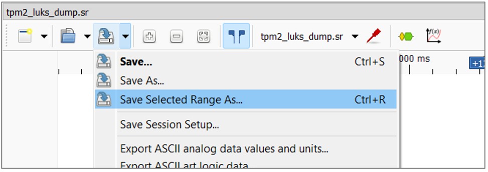
 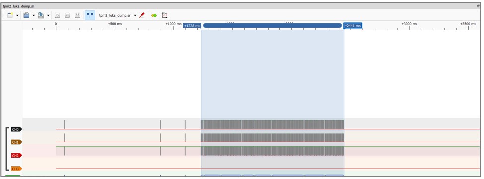 3. Save this waveform to a file via “Save Selected Range As...”:
  4. Open the newly created file.
 5. Add a TPM signal analyzer plug-in to the waveform. To do this, it's required to:
a. Click “Add protocol decoder” button:
b. Find the TPM plugin on right sidebar:
c. Select SPI in the window.
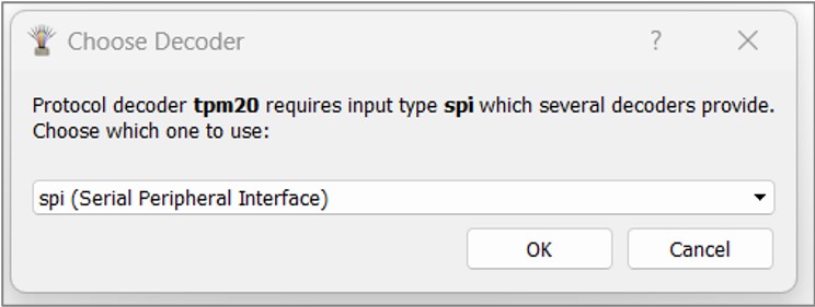 d. Click on the TPM waveform.
 e. Configure the SPI signals according to the actual state. Indicate which channels of the logic analyzer are connected to which pin of the TPM:
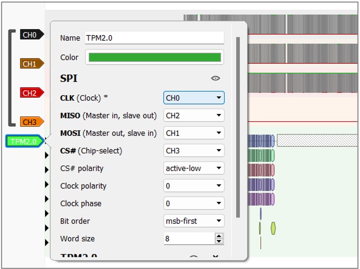 6. When the plug-in analyzes the waveform, the data obtained in the “TPM2.0: FIFO Read” line should be exported to a .txt file.
 7. Next, a special script will be used to extract the JSON Web Key (JWK) from .txt file, which is used by Clevis to decrypt the encryption password during system startup:
a. Save the following content to a file named extract_jwk.py:
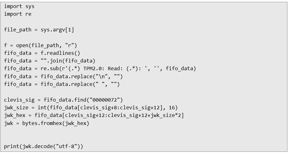 8. Then execute the script, where the path to the exported .txt file should be given as an argument:
  9. One by one, this script cleans up the data from the time tags, converts the contents of the .txt file into a continuous hex record, and then searches for the 00000072 bytes that mark the start of the JWK in communication with the TPM. It then takes the next two bytes that mark the size of the JWK and extracts its contents.
 10. Next, you need to extract the LUKS token for Clevis, this can be done using the following script. The token is the public information storing the decryption password and is located on disk. The attacker can pull this drive from the computer and put it into his own, and then pull the token:
 11. Then run the following script to get the password. This script combines the JWK (encryption key) and JWE (ciphertext), and then decrypts the disk password using the jose tool:
  12. Finally, to unlock the drive, run the following command:
  The penetration test demonstrated that SPI Sniffing is a viable attack vector, allowing an attacker with physical access to intercept communication between the TPM and processor, ultimately compromising the encryption keys used by Clevis or BitLocker. This vulnerability stems from the lack of secure communication protocols on the SPI bus, exposing sensitive data during the decryption process. Summary To mitigate this risk, systems should implement encrypted communication on the SPI bus or alternative secure methods for key exchange. Additionally, physical access to devices must be restricted through stronger physical security measures. Ensuring firmware is up-to-date and adopting hardware with enhanced protection mechanisms, such as Secure Boot, can further safeguard against such attacks. These measures collectively enhance the resilience of encryption systems against physical compromise.
 #PenetrationTesting #CyberSecurity #RedTeam #DataSecurity #Infosec #SecurityResearch
Next Pentest Chronicles

When Usernames Become Passwords: A Real-World Case Study of Weak Password Practices
Michał WNękowicz
9 June 2023
In today's world, ensuring the security of our accounts is more crucial than ever. Just as keys protect the doors to our homes, passwords serve as the first line of defense for our data and assets. It's easy to assume that technical individuals, such as developers and IT professionals, always use strong, unique passwords to keep ...

SOCMINT – or rather OSINT of social media
Tomasz Turba
October 15 2022
SOCMINT is the process of gathering and analyzing the information collected from various social networks, channels and communication groups in order to track down an object, gather as much partial data as possible, and potentially to understand its operation. All this in order to analyze the collected information and to achieve that goal by making …

PyScript – or rather Python in your browser + what can be done with it?
michał bentkowski
10 september 2022
PyScript – or rather Python in your browser + what can be done with it? A few days ago, the Anaconda project announced the PyScript framework, which allows Python code to be executed directly in the browser. Additionally, it also covers its integration with HTML and JS code. An execution of the Python code in …


